| Ñ .E=0 Ñ .H=0 Ñ×E=-µ |
|
Ñ×H=e |
|
(4.1) |
| Ñ2E=µe |
|
(4.2) |
|
=cm= |
|
<c (4.3) |
| n= |
|
>1 (4.4) |
| D.dS=0 |
| EI=E | I0e |
|
| ER=E | R0e |
|
| ET=E | T0e |
|
| H= |
|
| E | I0e |
|
+E | R0e |
|
=(ET0)t=(constant) |
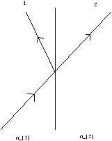
| sinqI= |
|
| sinqR= |
|
| kI2= |
|
= |
|
|
=kT2 |
|
| kT=± |
|
kI |
| EI=E | I0e |
|
| ER=E | R0e |
|
| ET=E | T0e |
|
| H= |
|
(classwork three) |
| HI= |
|
= |
|
(kI×y) |
| HI= |
|
(cos(qI)x+sin(qI)z)×y |
| HI= |
|
(-sin(qI)x+cos(qI)z) |
| HR= |
|
(-sin(qI)x-cos(qI)z) |
| HT= |
|
(-sin(qT)x+cos(qT)z) |
|
cosqI- |
|
cosqI= |
|
cosqT (4.14) |
|
= |
|
(4.15) |
|
= |
|
(4.16) |
|
= |
|
(4.17) |
|
= |
|
(4.18) |
| R= |
|
| R= |
½ ½ ½ ½ |
|
½ ½ ½ ½ |
| <N>= |
|
k (handout 4) |
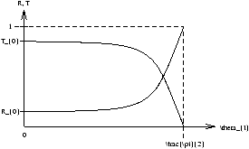
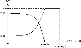
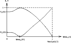
| R= |
|
= |
|
(4.19) |
| T= |
|
| T= |
|
= |
æ ç ç è |
|
ö ÷ ÷ ø |
|
(4.20) |
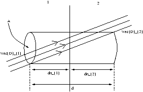
| sinqT= |
|
sinqI |
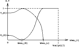
| qC=sin-1 |
|
| kT2=kTx2+kIz2= |
æ ç ç è |
|
ö ÷ ÷ ø |
|
kI2 |
| kTx2= |
æ ç ç è |
|
ö ÷ ÷ ø |
|
kI2-kIz2 |
| kTx2= |
æ ç ç è |
|
ö ÷ ÷ ø |
|
kI2 |
æ ç ç ç ç ç è |
1- |
æ ç ç è |
|
ö ÷ ÷ ø |
|
ö ÷ ÷ ÷ ÷ ÷ ø |
sin2qI |
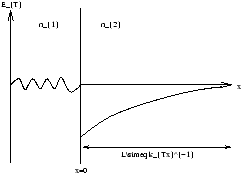
| E | T=ET0e |
|
e |
|
(4.21) |