Chapter 7 Guided Electromagnetic Waves
Feymann Chapter 24
Dobbs Chapter 14
Duffin Chapter 10.10 and 14.4
7.1 Introduction
We will be covering how to guide electromagnetic waves. Some examples are
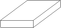
Waveguides (hollow conductor):
can typically accept frequecies of 1
®
300
Ghz
and can be of length 1
mm
®
30
cm
Figure 7.1 - A Hollow Conductor
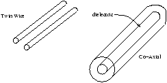
Transmission Lines (conductor and dielectric):
there are two types of transmission lines:
Twin Wire:
accepts a direct current of frequency 10
kHz
and has a maximum length of about 3× 10
4
m
Co-Axial:
can take a signal of about 100
Hz
®
1
GHz
to a distance of about 30
cm
Figure 7.2 - Two Types of Transmission Line
Optical Fibres (dielectrics):
accept frequencies in the range of the Infrared to Visible light region
Figure 7.3 - Optical Fibre
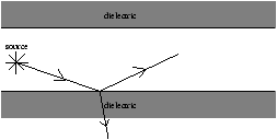
We will consider only transmission lines and waveguides. The two ways we cound guide the power is with dielectrics and metals
Figure 7.4 - A Dielectric Transmission System
In the case of a dielectric there is loss of power, so the signal gets weaker and cannot travel long distances.
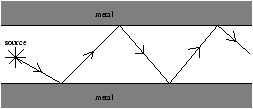
Figure 7.5 - A Metal Transmission System
In the case of the metal the signal is just reflected and the power is confined within the transmission system, the signal maintains its strength.
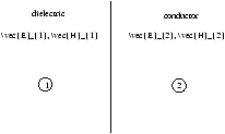
7.1.1 Boundary Conditions at a Perfect Conductor
The electric and magnetic fields penetrate as
d
µ
s
-
1/2
. We assume that
s
®
¥
so that
d
®
0 . So
E
.
H
=0 in a conductor.
Figure 7.6 - Boundary Conditions of a Perfect Conductor
So equations 4.5 to 4.8 are
D
n
1
=
s
(7.1)
E
t
1
=0 (7.2)
B
n
1
=0 (7.3)
H
t
1
=
j
s
(7.4)
where
s
is the surface charge density (
cm
-2
) and
j
s
is the surface current density (
Am
-1
).